1. Having basic knowledge of Excelsheet.
2. Having Aspen Plus installed on your computer
3. Having a desire
How do I calculate line size?
Line sizing is a trial-and-error process. In reality it is performed based on design criteria for each project. If it is done by Excel or Aspen or other simulation software, then the process engineer should at first estimate the pipe diameter and then chech the calculated pressure drops and velocity against the design criteria.
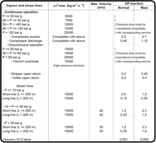
What is the pressure drop in line sizing?
The pressure drop in line sizing varies from application to application. For example, for some applications like pump suction it might be 2.3 bar/km while for a gas application the acceptable pressure drop might be as low as 0.2 bar/km.
What is the velocity criteria in line sizing?
Based on different applications the velocity varies from application to application. But as a normal practice the velocity of gasious fluids is between 10 to 20 m/s while the velocity of liquid is between 1.5 to 4.5 m/s.
What is a governing factor in line sizing?
There are two parameters which determine and impact line sizing-that is- velocity and pressure drop. Each has their own limitation and process engineers should select a pipe diameter in which the pressure drop and velocity of fluids meet the criteria.
In this part the trainer familarize learners with Design Criteria used for line sizing of gas applications and liquid and two-phase applications.
Overview
This paragraph shall not be applied to the flare lines. The pressure drop and velocity guidelines provided may be used for the preliminary sizing of lines. However, the final sizing shall also take into account other factors, such as pump NPSH requirements, pressure drops available, and specific process requirements.Where specific maximum velocity limits are given these shall not be exceeded.
Notes:
1) 3.0 m/s maximum (2 m/s average) at storage tank inlet or in loading.
2) Vendor and/or Licensor requirements could supersede maximum velocity values upon
COMPANY approval.
3) Special considerations can be applied for copper-nickel or glass reinforced plastic piping
uponCOMPANY approval.
4) Velocities below 1 m/s shall not be used for cooling water service to avoid solids deposition.
5) For amine service velocity should not exceed 1 m/s to avoid corrosion/erosion.
6) For lines containing mixtures of hydrocarbon and water, velocity should be limited to 1 m/s to
avoid generation of static.
7) 60 to 98% sulphuric acid lines velocity should not exceed 1.2 m/s to avoid corrosion.
Line sizing criteria for two phase flow
In this part the instructor teaches how Excel could be used to calculate pressure drop,velocity, and velocity head. Then he performs three trials to calculate the optimised diameter for the pipe by comparing the results with Design Criteria.
Overview
In engineering companies it is typical to use Excel for preliminary calculation of pipe ID. The procedure is like this :
At first the process engineer selects a diameter using the excel shown in the video; then the pressure drop, velocity and velocity head are calculated. Now the process engineer compares the results with velocity, pressure drop and velocity head criteria by using Tables shown in the video. Since the results exceed the criteria the process engineer has to increase the diameter till the criteria are met. By using the excel for each pipe segment it only takes 2 minutes to find the right ID for a specific pipe segment.
In this part the instructor teaches how Aspen plus could be used to calculate pressure drop,velocity, and velocity head. Then he performs three trials to calculate the optimised diameter for the pipe by comparing the results with Design Criteria.
Overview
In engineering companies it is typical to use Aspen Hysys or plus beside Excel to verify calculation of pipe ID. The procedure is like this :
At first the process engineer reaches a preliminary ID for a pipe segment.Now he uses Aspen plus to calculate pressure drop, velocity and velocity head in a rigorous way. Then he uses the same criteria and check the results against the criteria and eventually finalizes the pipe ID.
In last part the trainer talks about his experience with line sizing.