1. Basic Math and Excel Skill
2. Have a Computer
3. Have a Desire
1.What is a seperator?
A pressure vessel designed to divide a combined liquid–gas system into individual components that are relatively free of each other for subsequent disposition or processing.
2.What are the different types of separators?
Separators are usually characterized as vertical, horizontal, or spherical.
3.How do you size a separator?
Design Procedure for seperators is the following:
1.Select proper Orientation
2.Select and Size proper Inlet Device, Inlet and Outlet ID
3.Calculate Vessel Diameter based on Saunders-Brown K-value
4.Calculate Vessel Height
5.Select and Size Manholes, Vent, Drain, Vortex Breaker
6.Select a well-designed mist eliminator pad
4.What is the difference between vertical and horizontal separators?
The criterion to select the orientation of the vessel is application-based. While for the application which is gas dominant vertical orentiation is selected, for the application which is liquid dominant horizontal orientation is selected. Horizontal orientation offers a higher interface between liquid and dissolved gas.
Why vertical orientation is selected for the compressor suction drum based on GPSA Table.
Overview
Factors that Determine Vessel Orientation
| Feature | Vertical | Horizontal |
|---|---|---|
| Compact Separators | Yes | Yes |
| Small Footprint | Yes | _ |
| Small Liquid Surge Drums | Yes | _ |
| Solids Removal with Liquid | Yes | _ |
| Small Capacity Flare K.O. Drums | Yes | _ |
| Gas Dominated Service | Yes | _ |
| Liquid Dominated Services | _ | Yes |
| Three-Phase (G/L/L) Separation | _ | Yes |
| Liquid-Liquid Separation | _ | Yes |
| High Liquid Degassing Residence Time | _ | Yes |
| Pigging & Slug Flow Separation | _ | Yes |
| Foaming Feeds | _ | Yes |
| High Liquid Surge Capacity | _ | Yes |
| Large Capacity lare K.O. Drums | _ | Yes |
| Solid Removal Thriugh Jetting | _ | Yes |
| High Vapor and Liquid Flow Rates | Yes | Yes |
Why half-open pipe is selected and what the downstream criteria are, by means of which liquid and vapor outlet nozzles are sized.
Overview
How Inlet section can impact seperation?
The first stage, primary separation, uses an inlet diverter so that the momentum of liquid
entrained in the vapor causes the largest droplets to impinge on the diverter and then drop by
gravity.
Inlet Devices — Proper selection of the inlet device is critical in separator design. Inlet
devices should reduce the momentum of the inlet stream, initiate gas-liquid separation
with minimum creation of fine droplets, and distribute gas flow evenly throughout the
inlet and gravity separation section of the vessel
There are several types of inlet devices used in the industry. The more common devices are
shown below.
Overview
The next stage, secondary separation, is gravity separation of smaller droplets as the
vapor flows through the disengagement area.For secondary separation, the allowable velocity
must be calculated so that the disengagement area can be subsequently determined.
Performing a force balance on the liquid droplet settling out provides the necessary relationship. When the net gravity force ![]() the drag
the drag ![]() force . The heavier liquid droplets will settle at a constant terminal velocity. Equating these two forces results in
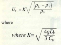
force . The heavier liquid droplets will settle at a constant terminal velocity. Equating these two forces results in 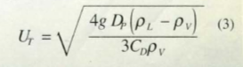 Here as long as Uv < UT the liquid droplets will settle out. Typically, the allowable vertical velocity Uvis set between 0.75 UTand UT. This could be rearranged to a Saunders-Brawn equation.
In vessels with no internals, gravity settling is the only mechanism of separation. Thus, terminal velocity of the minimum particle size desired for separation is critical. For vertical vessels, a liquid droplet will settle out of the gas phase when the vertical gas velocity is less than the droplet’s terminal velocity. The terminal droplet velocity can be obtained by using the appropriate settling law expression, or an industry experience K value. The target droplet diameter, or K value, is selected to prevent excessive entrainment based on experience. In either case a target droplet size of about 250 to 500 microns is typically used for many gas liquid gravity separator designs.
Know how to Select a well-designed mist eliminator pad using KG TOWER software.
Overview
Gas Polishing Section
Selection of the appropriate device for gas polishing should be based on consideration of the
application, operating pressure, likely feed droplet size range, allowable downstream
carryover requirement, and the relative acceptability of the user for more compact and
complex solutions.
Mechanism of Mist Carryover for Gas-Liquid Mist Eliminator Devices
Mist eliminators are commonly used in gas-liquid separation to aid gravity separation in the
removal of liquid so that more efficient, smaller separators may be used. To be effective, a
mist eliminator must accomplish two basic functions. First, it must have a means to capture
liquid. Second, it must be able to drain the captured liquid without allowing re-entrainment into
the gas streams. There are two mechanisms of liquid carryover from a mist eliminator. In the
first mechanism, carryover is due to droplets of mist which are simply not captured by the
device. The droplets might be too small to be captured or velocities are too low, causing low
efficiency for impaction-type mist extractors. The second is re-entrainment of liquid after it has
already been captured in the mist eliminator.
What are different types of mist eliminators?
The most common style of mesh mist eliminator used in gas processing is a 100 mm to 150
mm thick crimped wire mesh pad with 144 to 192 kg/m3 bulk density. High droplet removal
efficiency for droplets 10 microns and larger is common for the above design. Other designs
include fiber mesh, mixed wire and fiber mesh, multiple mesh density layers, and special
drainage channels. The goals are either to increase removal efficiency at lower droplet
diameters, promote better drainage and in turn less carryover, increase throughput for a given
mist eliminator area, reduce fouling, or a combination of the above. Manufacturers should be
contacted for specific designs. Mesh pads are not recommended for dirty or fouling service as
they tend to plug easily and can dislodge at high differential pressure.
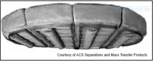
Wire Mesh Mist Eliminator
Vane Mist Eliminators
Vane or chevron-type mist eliminators (vane-pack) use relatively closely spaced blades
arranged to provide sinusoidal or zig-zag gas flow paths. The changes in gas flow direction
combined with the inertia of the entrained liquid droplets cause impingement of the droplets
onto the plate surface, followed by coalescence and drainage of the liquid to the liquid
collection section of the separator. Vane packs may be installed in either horizontal or vertical
orientations. Various vane styles are available, including those with and without pockets (both
single and double pockets) to promote liquid drainage.