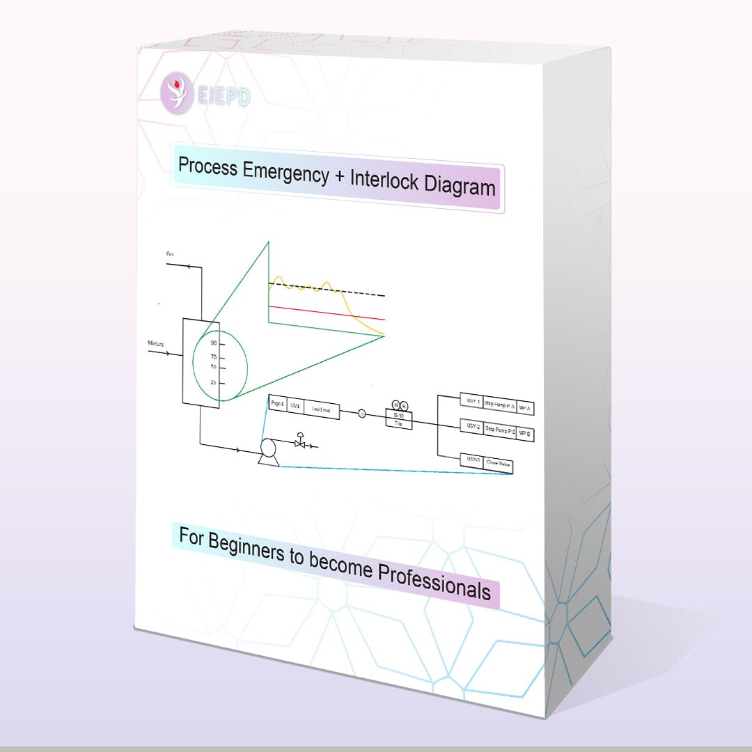
The process plant design without taking into account preventive measures which safely shut-downs the plant is literally meaningless. Process emergency description and cause and effect matrix (interlock diagram) are the documents which should be developed by process department during basic design and later be detailed and implemented during project phase in FCS and ESD.
Who should take the course?
1. Process engineers
2. Control system and instrument engineers
3. Control room operators
4. Chemical engineers
Introduction
Session 1: Purpose and preparation procedure
Session 2: Example 1
Session 3: Example 2
Auto-Cad Training
1
Process Emergency + Interlock for Equipment
Session 4: Pumps
In this session the presenter provides different examples through which you will learn:
1. In first example you learn a simple cause and effect for a centrifugal pump for a simple application. You also are taught where and when to use such pattern.
2. In second example you learn a simple cause and effect for a reciprocating pump for a simple application and as a result you get to the understanding that there is no difference between reciprocating and centrifugal pumps when it comes to cause and effect diagrams.
3. In third example you learn that for some pumps more causes should be included to safeguard the pumps.
4. In forth example you learn how cause and effect for pumps for product export pumps differs.
Now the instructor provides interlock diagram of pumps used in different water applications such as boiler feed water, boiler blow-down, de-mineralized water, and cooling water.
5. In fifth example you are taught which cause should be added to cause and effect diagram when dealing with boiler feed water pumps.
6. In Sixth example you get familiar with causes of cooling water pumps trips.
7. In seventh example you are taught which causes trip the DMW pump.
8. In eighth example you see what causes trip boiler blow-down pumps.
You see we give a number of examples not to teach you how to draw interlock diagrams but to familiarize your mind with different causes tripping pumps in different applications. If the objective was the first one, we reach that in introduction part!
Now the speaker continues with more amazing examples which provides instruction on auto-start of pumps:
9. In this example you are taught how to prepare interlock diagram for auto-start of a pump. In first part, an introductory example was given about auto-start of a pump but in this example another cause is added.
10. In this example you learn that it is always not the downstream pressure that auto-starts the standby pump; sometimes flow could trigger the standby pump.
11. In this example you are taught how to prepare and develop the interlock for auto-start and auto-stop of the closed drain pumps which is common in almost in each process plants.
Practice: You are supposed to develop process emergency description and cause and effect diagram for bottom of a distillation column.
Session 5: Separators
We start with developing process emergency description and cause and effect for knock-out drum which is located at the inlet of most petrochemicals.
In second example, interlock diagram is developed for a simple low-pressure drum.
In third example it is shown how activation of one interlock can lead to activation of another interlock, tripping the liquid inlet to the tank.
Session 6: Reactor
The first thing that comes to our mind about reactor control is temperature control. In first example you are taught how a simple interlock can prevent some unwanted byproducts or damage to the catalysts.
In second example which is more difficult the technology of ATR reactor is discussed. The ATR reactors have been widely used for modern methanol plants, ammonia plants and conventional hydrogen plants. You are taught how such interlock can preclude catastrophe in such reactor.
Session 7: Fans
You will learn the followings:
1. Interlock for cooling tower fans
2. Interlock for FD fan and ID fan of fired heaters
Session 8: Tanks
In first example you are taught which causes and effects you as process engineer should include in your interlock diagrams when dealing with crude or raw product storage tanks. Then in second example you see sometimes how developing process emergency description and interlock diagram for storage tanks could become complicated although the process is very simple.
Session 9: Compressors interlock and logic diagram
In first example the presenter provides typical interlocks for compressors.
In second example the instructor empowers and specializes learners so much that they can develop logic diagram for a compressor. In second example you will learn:
1. The basic of logic diagram and how it differs from interlock diagram.
2. Applying aforementioned rule for developing logic diagram for a nitrogen compressor whose function is to purge a reactor loop with nitrogen.
Session 10: Filters
Filters are essential part of most treatment facilities including polishing units, cooling water units and RO units. In this example you are taught how an interlock can help you backwash the filters on time.
Session 11: Valves
In first example it shown how implementing an interlock on a valve could adjust the process parameters. In second example the function of the valve is much more important and the interlock should be meticulously designed to prevent any disaster.
Session 12: Fired heaters
In this session typical causes and effect for refinery and petrochemical fired heaters are stated and subsequently the interlock diagram is developed accordingly.
Process Emergency + Interlock for Processes and Packages
Session 12: Polishing Unit
You can find polishing units in almost all process plants; in this regard, the instructor at first gives instruction on PFD of a typical polishing unit and then starts preparing process emergency description document for the whole unit. He then develops cause and effect diagram (interlock diagram) based on process emergency description document. In this manner, the learners become fully prepared for similar projects and units.
Session 13: Turbine
Process engineers always like to know how the logic in PLC for turbines works. We make your wishes come true. You will be proud of yourself after this session that you have gained so much knowledge about turbine logic diagram of a BFW pump.
Session 14: Cooling Tower
Simply the speaker starts the session with giving the instruction on cooling water PFD and subsequently, providing process emergency description document and interlock diagram accordingly.
Process Emergency + Interlock for a Process Plant
Session 15: Project review
At this stage, to make sure the participants have understood all elements, all participants are assigned with preparation and development of process emergency document and interlock diagram for the whole units of a process plant. It is obvious that they are taught about PFD of that particular plant.
Project
This part has two sessions, in first session, the instructor does a project similar to the one you are supposed to do and in second session, the instructor does the project you were supposed to do!
Session 12: The whole month in one project
You will learn the followings:
1. Pump simulation in Aspen Plus
2. Preparation and development of pump datasheet to a fully-fledged state.
3. Valve simulation in Fisher software and Aspen Plus and their comparison
4. Preparation and development of valve datasheet to a fully-fledged state.
5. PFD development
6. P&ID development
7. ” Process Emergency Description” document and Interlock diagram development.
Detailed Engineering
Session 13: detailed P&ID development around equipment and their design notes
In this session we go beyond typicality and discuss the followings:
1. P&ID development for pumps for different applications.
2. P&ID development around air cooled heat exchangers
3. Vent and drain systems
4. Miscellaneous piping arrangement
Session 14: Separator Design
In this session we will size a vertical separator with mist eliminator using excel-sheet and KG-Tower.
Session 15: PSV Sizing
In this session we will instruct the followings:
1. How to calculate the relief load for different scenarios (control valve failure, tube rupture and fire) using Aspen Hysys Safety Environment.
2. How to determine orifice area, designation on the P&ID and prepare datasheet.
Session 16: Shell and tube heat exchanger sizing
In this session you will learn the followings:
1. Not only understanding but also deepening your knowledge in using TEMA standard.
2. Thorough comprehension upon HTRI and how to manipulate it to its full potential.
3. Sharing our experience in a systematic manner.
1. Are you able to prepare process emergency description for process units, utility units, and packages?
2. Are you able to draw cause and effect matrix (Interlock diagram) for pumps for different scenarios and applications?
3. Are you able to develop interlock diagram for fired heaters? Do you know which causes for fired heaters trip to be included in process emergency description?
4. Do you know what should auto-start a BFW pump?
5. How much do you know about the typical logic of a motor-driven compressor?
6. How much do you know about logic diagram (do not mistake it with interlock diagram)?
Be honest with yourself and for each question give yourself a score out of 10. If the sum is less than 30, then take the course; if the score is between 30 to 50, consult with us. If it is more than 50, we think you don’t need to take it.
1.The Process Emergency + Interlock Diagram course will be available in both online and offline modes to enthusiasts. By online mode, the enthusiasts can participate in online classes while by offline mode, the enthusiast can only watch offline videos after purchasing the package.
2.Notice that the enthusiasts who choose online mode will also receive offline package so that they can review what they have learned in online classes.
3.It is obvious that in both modes, the whole package including videos, documents, excelsheets will be provided.
The Process Emergency + Interlock Diagram [ Cause and effect ] course will be introduced to engineering community in two time-sets. For each group maximum 25 registrations are allowed, aiming to keep the quality high.
Group A
Saturdays at 20.15-22.45 Tehran Time from 17 February onwards. The course will end on 6 April 2024.
Duration: 19 hr.
We hope the selected time-sets suit you most.
We make you proud.