Who should take this course?
1. Process engineers
2. Control room operators
3. Chemical engineers
4. R&D engineers
In this session, the following subjects are addressed in a subsequent order:
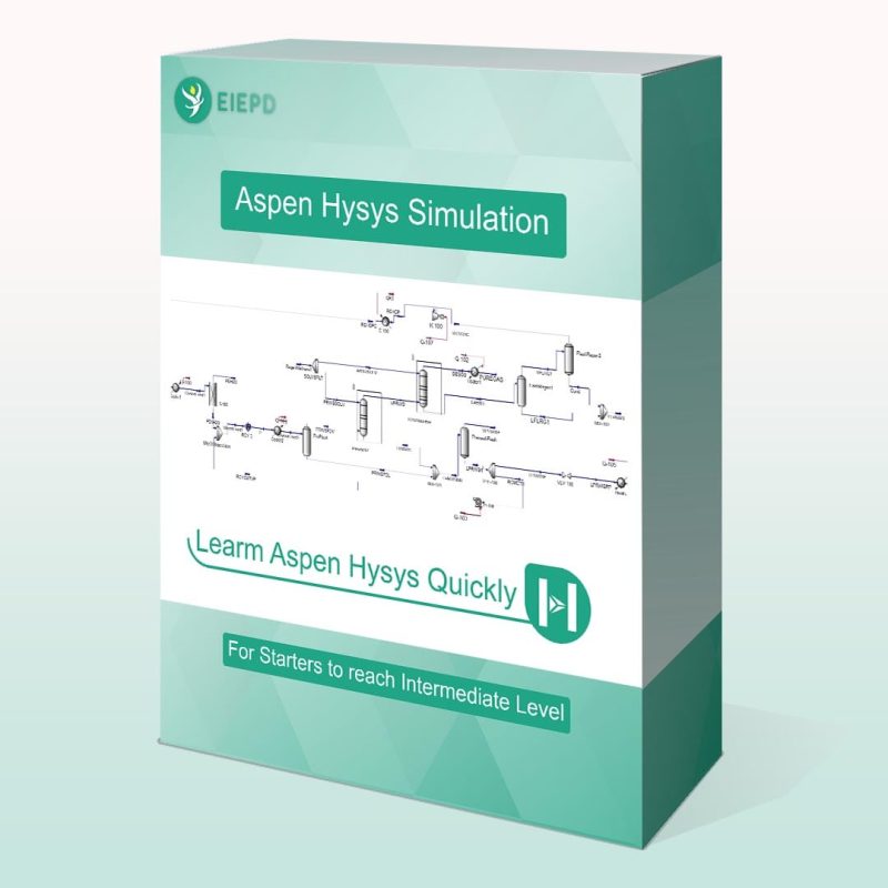
1. Environment of the software
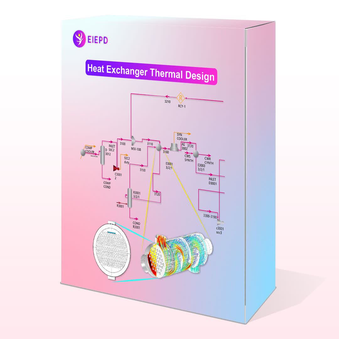
2. Elaboration upon process of the heat exchanger and process data including process condition, heating and cooling table.
3. Providing process conditions, heating and cooling tables to the software based on the data obtained from Aspen Hysys or Plus.
4. Specifying shell geometry (ID and orientation), tube geometry (type, length, tube OD, pitch and material) and baffle geometry (type, orientation, cut, spacing). In this regard, TEMA chapter 5 and Saunders handbook are used as guidance and reference.
5. Impingment (definition, criteria, and how it should be dealt with in the software)
6. Nozzles (standard, schedule, ID and OD, and shell-side nozzle location)
After providing above information, the software is run and the result is checked. Since the dp in the shell-side and overdesign factor are not satisfactory, the instructor, in first step, increases the shell ID, which results in a decrease in dp and an increase in overdesign factor. Then, he plays with baffle spacing to further reduces dp and increases the overdesign factor.
In order to reach an optimal design, he further shows how shell diameter, tube length, tube number should be changed so that simultaneously all parameters such as dp, overdesign factor, B-stream percentage, cooling water velocity are in perfect range.
At the end he elucidates the finalized drawings for different parts of the heat exchanger.
In this session, the following subjects are addressed in a subsequent order:
1. Environment of the software
2. Elaboration upon process of the heat exchanger and process data including process condition, heating and cooling table.
3. Providing process conditions, heating and cooling tables to the software based on the data obtained from Aspen Hysys or Plus.
4. Specifying shell geometry (ID and orientation), tube geometry (type, length, tube OD, pitch and material) and baffle geometry (type, orientation, cut, spacing). In this regard, TEMA chapter 5 and Saunders handbook are used as guidance and reference.
5. Impingment (definition, criteria, and how it should be dealt with in the software)
6. Nozzles (standard, schedule, ID and OD, and shell-side nozzle location)
7. Changing shell ID, tube length and their impacts on overdesign factor and pressure drops.
8. Flow-induced vibration analysis are comprehensively explained and the methods by which those vibration warning could be eliminated are elaborated upon.
In this session, the following subjects are addressed in a subsequent order:
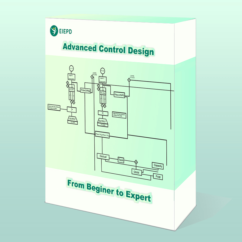
1. Process specification
2. Process input to software
3. The differences between and application for induced-draft and forced-draft fans are explained. Subsequently, induced-draft fan is selected according to the application.
4. At this stage, the instructor defines the bay and their structures; then, he explains different types of headers and their applications.
5. The criteria for fan clearance and fan ring types is discussed.
6. Bundle framework and temperature control over air-cooled heat exchangers are elaborated upon.
7. In this part, the instructor brings different fin types and their applications under scrutiny.
8. The guideline for tube size and pitch are given, based on which, OD and tube pitch are selected and given to the software.
9. Under the fin tab, it is shown how references could be used to determine fin density, fin height, fin base thickness and fin tip thickness.
The software is run and fails; then the instructor step-by-step increased the number of bays to 42; simultaneously, pressure drop and driver power for each trial are checked. Afterwards, in order to optimize the design, he increases fan efficiency to 75% and changes fan ring to cone 30.
Reboiler heat exchanger thermal design